Mantle Clock Project
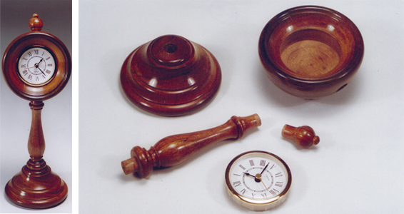
This elegant clock will make a very attractive addition to your mantelpiece or an equally acceptable present for someone who needs a bit of help with their timekeeping!
Although it looks like a simple project to make, there are actually a couple of tricky bits to overcome. The base and the stem are quite straight forward bits of turning and will not give any real problems, but the top section is a bit different. Firstly the face has to be held without leaving any sort of mark on the rounded back, and secondly there is some accurate drilling to do for both the stem and the top finial. These two holes must be drilled perfectly in line and truly at 180 degrees to each other, and both of them are drilled at a slight angle to the face, but both are slightly different angles.
So it�s really not that straightforward. But don�t worry, I shall show you how to make a simple jig to help with all this drilling, and also how to divide out to get the holes in the right place. You can buy all sorts of fancy bits of kit and accessories to do all this for you, but I think that half the fun of woodturning is to work round this sort of challenge yourself so we�ll make our own wooden jigs.


1. Preparation
To make the clock you will need 3 pieces of wood (fig.1), the base is 4�diameter by 2� thick, the stem is made from 7� of 1�� square, and the top section is 4� diameter by 2��. You�ll also need the clock as well, in this case a simple insertion movement 2� diameter.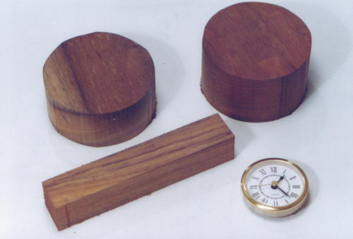
Fig 1. Materials Needed
Prepare the blanks and correct sized clock insert
2. Faceplate Mount
I prefer to do the difficult bit first so start with the top section. Decide which is to be the face, but remember that you need to be able to turn this, and the rounded back without leaving any sort of screwholes showing in the finished job. I think the simplest method of holding is to screw it on a faceplate initially, turn the face with the recess for the clock movement, and then remount this, using the recess, on a homemade jam chuck to turn the back. Don�t worry about leaving screwholes in the back from the initial mounting on the faceplate. If you are careful and only use short screws right on the outer edge of the faceplate the holes will get turned away when you shape the back. So screw the faceplate onto what will be the back (fig. 2), but it is very important that you use short screws that only protrude about 3/8� maximum, and make sure you use the outer ring of holes. I prefer to start them with a bradawl and screw them in without a pilot hole, letting them find their own depth. If you drill a pilot hole there is always a danger of drilling too deep and then not being able to clean up these holes when you shape the back. Try to use a blank that is pretty flat, or even better has been planed to get a really good seating.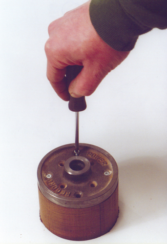
Fig 2. Attaching the Faceplate
3. Trim Up The Periphery
Now mount this on the lathe, and with the speed set at about 1500 rpm, trim up the periphery.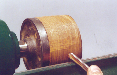
Fig 3
4. Marking up the Blank
To help position the holes for the stem and finial really accurately, scribe a line with a pencil on the revolving blank about �� in from the face (fig. 4), and also use the pencil to make a mark dead on the centre of the face.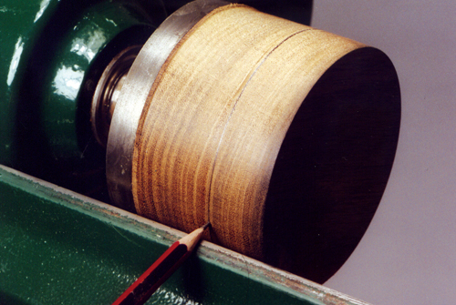
Fig 4
5. Mark Across the Centre
With the lathe now stopped draw a line across the face through this centre point.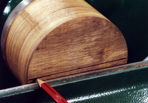
Fig 5
6. Mark up the Periphery
Now extend the ends of the line down the edge to cross the scribed line round the periphery. Just use a bradawl to clearly define these intersection points.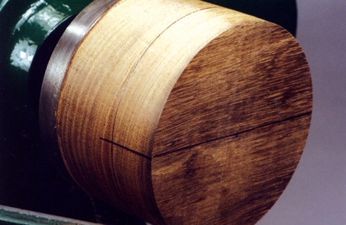
Fig 6
7. Make a Simple Drilling Jig
Now is a good time to drill these holes, and this is the slightly tricky bit. The holes have to be at right angles to the face axis of the blank, but at a slight angle to the edge to make it tilt back on the stem. The holes also have to be dead in line with each other; otherwise it all looks cockeyed when it�s assembled. You can try and line up and drill by eye, but it never really works, so just stop now and make a simple drilling jig, which will make the job foolproof. Start by taking a piece of 2.5� square material and turn a stem on it to be a snug fit in the toolrest holder, and mark the centerline of the remaining square section (Fig 7).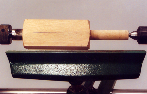
Fig 7
8. Mark for Drilling Reference
Place the stem into the toolrest holder and replace the faceplate with a centre point of some sort. It is usually better to use a sharply pointed tailstock centre, and then slide the holder along the bed to press the block onto this protruding point, getting it on the centerline (Fig 8). This leaves a drilling mark in the middle of the block, at exactly centre height, which is very important if the two holes in the finished clock are to line through accurately.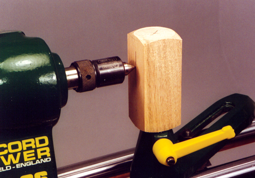
Fig 8
9. Using the Drill Press
Now take the jig out, and use your drill press to form a hole which is the size of the finished stem and finial spigots. I prefer to use the drill press for this because it is essential that the hole is dead straight in all planes. I am going to be using a 14 mm drill bit, in this case a bullet point type, to drill the holes in the clock, so use this to drill the jig as well, just drilling through at the centre point we have already marked.
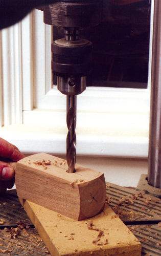
Fig 9
10. Drilling Jig
Replace the blank on its faceplate back on the lathe, and fit the jig into the toolrest holder. With it pushed right in we now know that this is dead on centre height, push the drill bit through the jig and set the angle we need, you can usually just do this by eye. Turn the lathe spindle by hand to line up the first drilling point with the end of the drill bit, the work you did with the bradawl earlier should help get the drill started in exactly the right place. Then drill to a depth of about 15 mm (Fig 10). Make sure you hold the block firmly as you drill, to stop it rotating, or the hole will be out of line. Then repeat the procedure for the other hole to take the finial, but in this case the angle doesn�t need to be so steep, so twist the jig back slightly in the toolrest holder. The finial needs to be almost at right angles to the top of the clock when viewed from the side, but with just a slight lean back.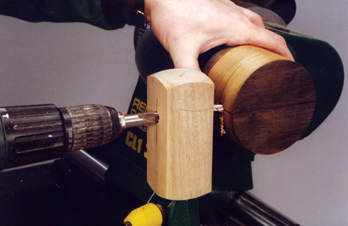
Fig 10
11. Turn the Face
With the holes successfully drilled, replace the toolrest and turn the face of the clock. I have dished this in slightly, and then formed the recess for the movement. Try and make this a tight fit, but not so tight that you cannot remove it to change the battery, or alter the time. It is probably better to also just carry the shaping round the back slightly to start forming the back profile, but don�t go too far or you will end up hitting the screws.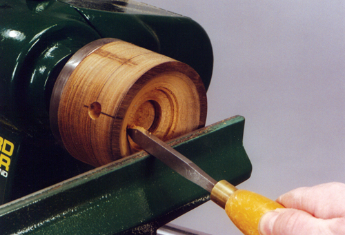
Fig 11
12. The Back Profile
Next mount a piece of scrapwood on a screwchuck and turn a long spigot to be a tight fit in the clock recess (Fig 12). Do try and make this spigot long or you will have difficulty accessing the front face of the clock when you come to the polishing stage later.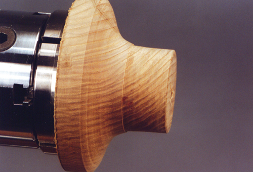
Fig 12
13. Turning the Back Profile
With the clock blank now firmly mounted on this jam chuck and the faceplate removed, it is a simple job to turn the back profile. In this case I am trying to get it as spherical as possible for the best effect. You can see now why we drilled the holes earlier on when it was much easier to judge relative orientation, and shaping now also means that the hole edges are really clean and not torn.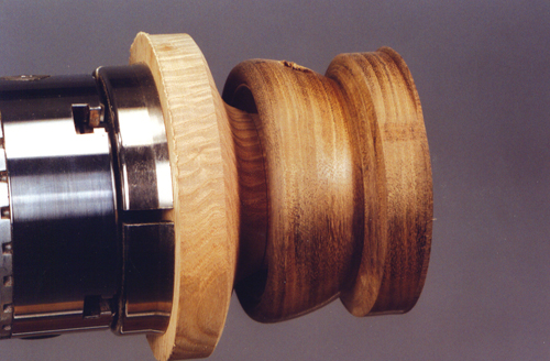
Fig 13
14. Finishing the Back Profile
When you are happy with the final profile, sand and polish it to whatever finish you prefer. Here I am using a cellulose sanding sealer and friction polish combination for a high gloss. If you have made the jam chuck long enough, and you relieve the shape of it slightly, you should be able to reach right round to polish the whole top section as one piece.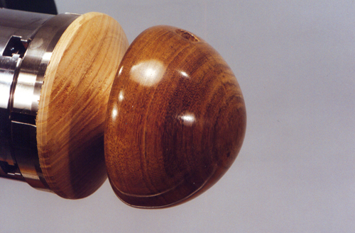
Fig 14
15. Begin the Base
The procedure for turning the base is very simple. Mount the blank on a screwchuck to turn the underside first. Form a dovetail recess.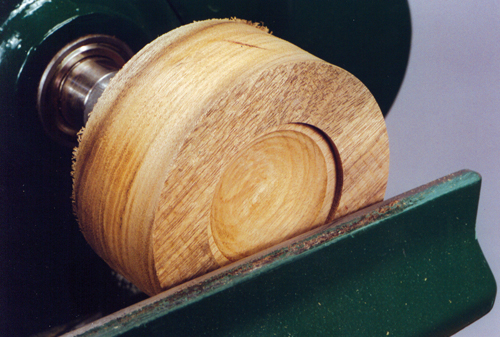
Fig 15
16. Re-Mount the Base
Reverse the wood onto the chuck, having first sanded and polished in the recess.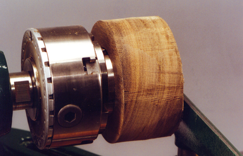
Fig 16
17. Finish and Drill the Base
Then shape the top of the base, and either turn a hole for the spigot on the end of the stem, or drill it using the tailstock chuck. For the sake of consistency I have again used a 14 mm drill bit, but the size isn�t critical. I have formed a tapered profile to try and blend the spindle into the base, without it obviously being two separate pieces of wood, but keep the overall section of the base quite robust to maintain the balance with the top. Again sand and polish to match the rest, and put this second component safely to one side.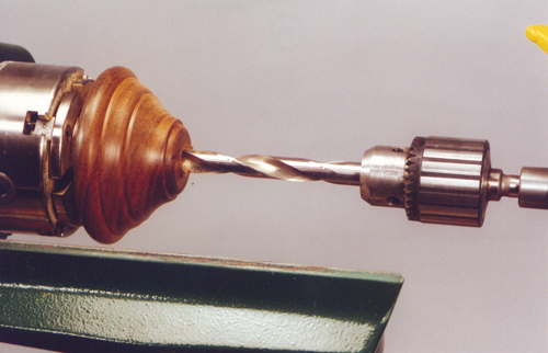
Fig 17
18. The Spindle & Finial
There is now only the spindle and finial to make, and I turn these in one piece to maintain the grain continuity. Just rough the spindle blank down to a cylinder, and turn a 14 mm diameter spigot on the left-hand end, long enough to be a good fit in the base. Decide how long you want the top finial to be, and mark this off from the right hand end, adding a few millimetres extra to allow for cleaning up. Using callipers, turn down a section at this point to 14 mm diameter and extend this diameter along the spindle for about 25 mm. When you later cut through in the middle of this parallel section it will form one end of the finial, and the other end of the spindle. Both bits need to be a tight fit in the clock section, so work accurately.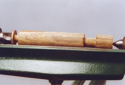
Fig 18
19. Final Shaping of the Spindle & Finial
With these spigots now defined, shape the rest of the spindle and finial, trying to join the bottom of the spindle to the base with a bead to hide the join. Finish this in the same way, and then part through at the junction of the two spigots.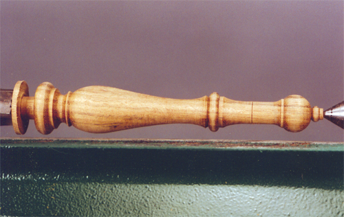
Fig 19
20. Assembly
Hopefully it should now all fit together, just clean up the top of the finial with a sharp chisel, and polish out the tiny marks remaining by hand. I use cyanoacrylate glue to assemble all the components, but take care to line up any strong grain patterns if at all possible. A good tip when you are gluing in these situations is to put the glue in the hole, rather than on the spigot, it just stops any oozing out onto the polished surfaces. If your jig has worked correctly everything should line up properly, and you now have a present to be proud of.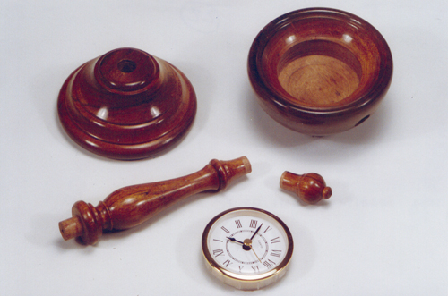
Fig 20
21. Tools Used for this Project
CH100 3/4” Roughing Gouge
CH200 1/4” Spindle Gouge
CH220 1/2” Spindle Gouge
CH500 1/8” Parting And Beading
CH601 1/4” Deep Bowl Gouge
CH700 1/2” Domed Scraper
CH900 3/4” Oval Chisel
CL3 Lathe, 5 Speed With Cam Lock Toolrest And Tailstock
CWA190 Speedaneez Friction Polish (Light)
CWA191 Speedaneez Friction Polish (Dark)


